

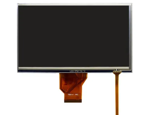
1) 10 inch 1024*600 TN LCD
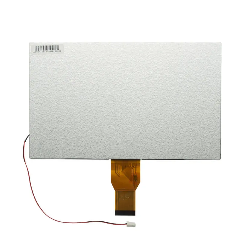
VIS101TN02 is a 10.1 inch TFT LCD display screen module model that adopts TN type LCD with a 1024*600 resolution. CTP (Capacity Touch Panel) and RTP(Resistive Touch Panel) can be added according to user requirements. Based on the substantial and long-term shipments of 10.1 inch LCD panels, we can guarantee a stable supply of this 10.1″ LCD display panel module throughout the life cycle of your product.
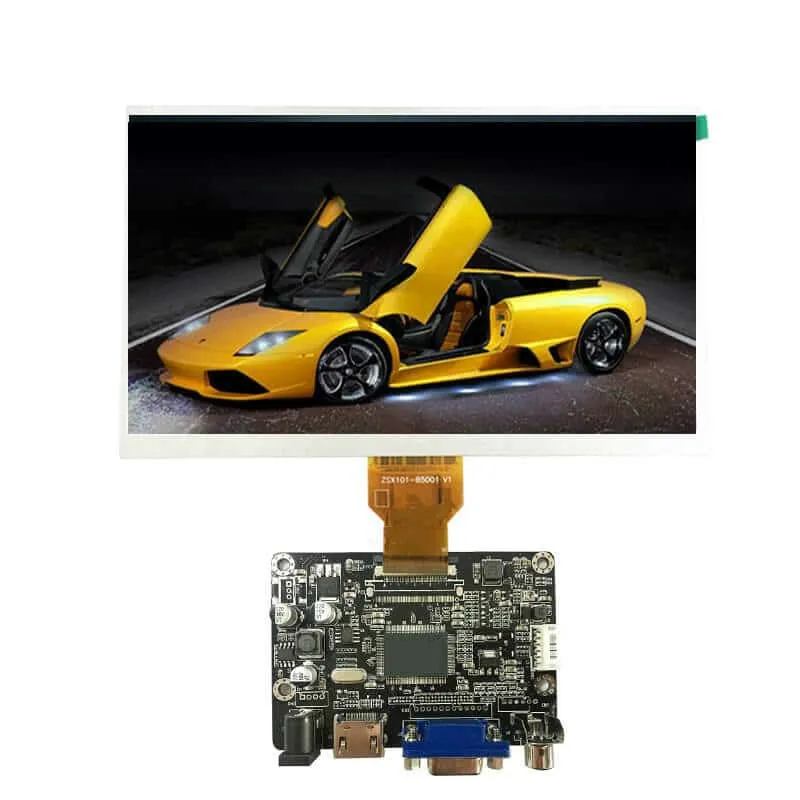
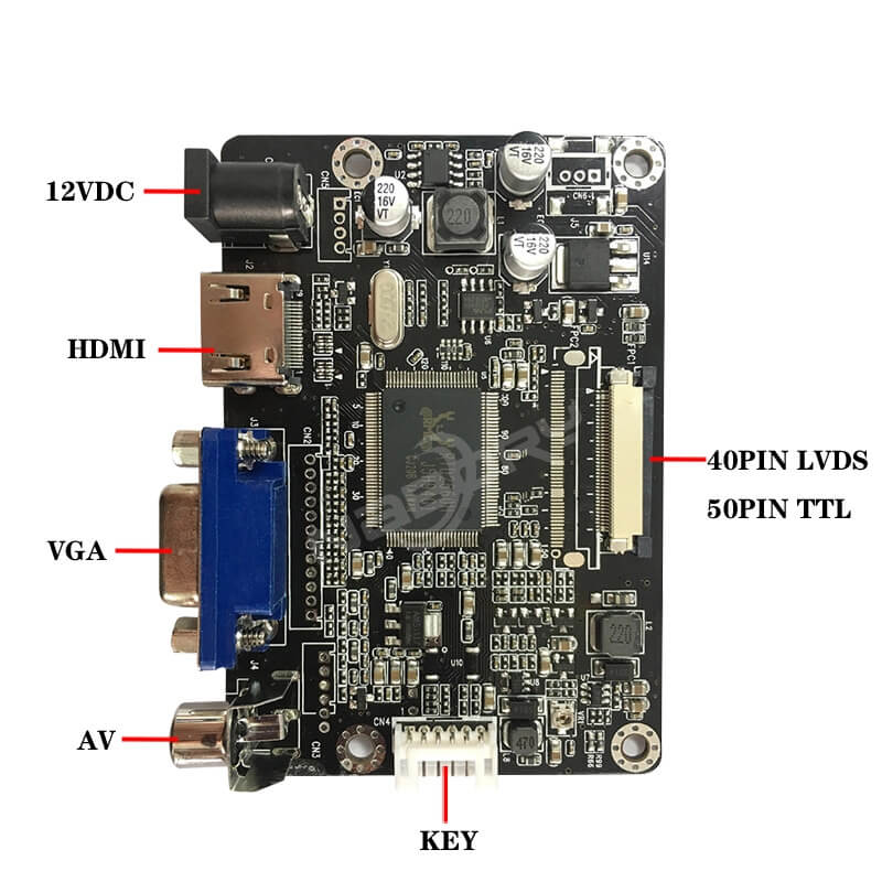
We also supply LCD with HDMI converter for your requirements.
Based on this LCD’s low price and high stability, this type of LCD display module can be widely used in smart homes, electronic restaurant menus, industrial instruments, vehicle displays, and other products.
FPCA pin defines & shape alignment, polarizer material, and backlight brightness can all be adjusted according to your needs.
We also provide a 10.1 ” LCD module with 1280*800 resolution products for your choice. If interested, please contact us for more information.
Other 10.1 inch TFT LCD Display Screen Module(LCM) models(1024*600) that can be replaced by VIS101TN02 are G101STN01, M101NWT2, N101LGE-L11 (CMO1032), TM101DDHG01, etc.
| Panel From | AUO/IVO |
|---|---|
| Panel Size | 10.1 inch |
| Panel Model | A101STN01, C101NWTG |
| LCM Model | VIS101TN02 |
| Panel Type | a-Si TN TFT-LCD, LCM module |
| Resolution | 1024(H) X 600(V) |
| Luminance | 350 cd/m² (Typ.) |
| Display Area | 222.72*125.28(mm) |
| Outline | 235.00*143.00*5.00(mm) |
| Interface Type | 40 pins LVDS |
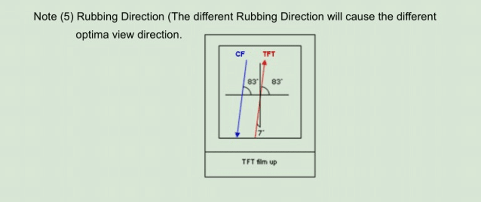
| View Direction | 6 o’clock |
| Touchscreen | Optional |
| Operating Temperature | 0 ~ 50 °C |
| Storage Temperature | -20 ~ 60 °C |
| Item | Contents | Unit | Note |
| LCD Type | TFT | – | |
| Display color | 16.7M | ||
| Viewing Direction | 12 | O’Clock | |
| Gray scale inversion direction | 6 | O’Clock | |
| Operating temperature | -0~+50 | ℃ | |
| Storage temperature | -20~+60 | ℃ | |
| Module size | Refer to outline drawing | mm | |
| Active Area(W×H) | 222.72X125.28 | mm | |
| Number of Dots | 1024×600 | dots | |
| Controller | HX8282A14+HX8696 | – | |
| Power Supply Voltage | 3.3 | V | |
| Outline Dimensions | Refer to outline drawing | – | |
| Backlight | 3X13-LEDs (white) | pcs | |
| Weight | — | g | |
| Interface | LVDS | – |
2. Absolute Maximum Ratings(Ta=25℃) 2.1 Electrical Absolute Maximum Ratings.(Vss=0V ,Ta=25℃)
| Item | Symbol | Min. | Max. | Unit | Note |
| Power Supply Voltage | VDD | -0.3 | 5.0 | V | 1,2 |
| AVDD | 6.5 | 13.5 | V | ||
| VGH | -0.3 | 42.0 | V | ||
| VGL | -20 | 0.3 | V | ||
| VGH-VGL | – | 40.0 | V |
Notes:
- If the module is above these absolute maximum ratings. It may become permanently
Using the module within the following electrical characteristic conditions are also exceeded, the module will malfunction and cause poor reliability.
- VCC >VSS must be
2.2 Typical operation conditions
| Item | Symbol | Values | Unit | Remark | ||
| Min. | Typ. | Max. | ||||
| Power voltage | VDD | 3.0 | 3.3 | 3.6 | V | |
| AVDD | 10.2 | 10.5 | 10.8 | V | ||
| VGH | 20 | 21 | 22 | V | ||
| VGL | -5.0 | -5.5 | -6.0 | V | ||
| Input signal voltage | VCOM | 3.3 | 3.7 | 4.2 | V | |
| Input logic high voltage | VIH | 0.7 VDD | – | VDD | V | |
| Input logic low voltage | VIL | 0 | – | 0.3VDD | V | |
2.3 Environmental Absolute Maximum Ratings
| Item | Storage | Operating | Note | ||
| MIN. | MAX. | MIN. | MAX. | ||
| Ambient Temperature | -20℃ | 60℃ | 0℃ | 50℃ | 1,2 |
| Humidity | – | – | – | – | 3 |
- The response time will become lower when operated at low temperatures.
2. Background color changes slightly depending on ambient temperatures. The phenomenon is reversible.
- Ta<=40℃:85%RH MAX.
Ta>=40℃:Absolute humidity must be lower than the humidity of 85%RH at 40℃. 3. Electrical Specifications and Instruction Code 3.1 Electrical characteristics(Vss=0V ,Ta=25℃)
| Parameter | Symbol | Condition | Min | Typ | Max | Unit | Note | |
| Power supply | VCC | Ta=25℃ | 3.0 | 3.3 | 3.6 | V | ||
| Input voltage | ‘H’ | VIH | VCC=3.3V | 0.8VCC | – | VCC | V | |
| ‘L’ | VIL | VCC=3.3V | 0 | – | 0.2VCC | V | ||
| Current Consumption | ICC1 | Normal mode | – | 50 | – | mA | 2 | |
| ICC2 | Sleep mode | – | 0.2 | – | mA | 2 | ||
| Clock Frequency | fCLK | – | – | 50 | – | MHz | ||
Note: 1:When an optimum contrast is obtained in the transmissive mode — 2: Tested in 1╳1 chessboard pattern. 3.2 LED backlight specification(VSS=0V ,Ta=25℃)
| Item | Symb ol | Condition | Min | Typ | Max | Unit | Note |
| Supply voltage | Vf | If=20X13mA | – | 9.0 | – | V | |
| Uniformity | ΔBp | If=20X13mA | 70 | % | |||
| Luminance for LCD | Lv | If=20X13mA | – | 350 | Cd/m2 | ||
| Life Time | T | If=20X13mA | – | 30000 | Hours |
3.3 Interface signals
| Pin No. | Symbol | I/O | Function |
| 1 | VCOM | P | Common voltage |
| 2-3 | VDD | P | Power for digital circuit |
| 4 | NC | – | No connect |
| 5 | REST | I | Global reset pin |
| 6 | SBYB | I | Stand mode: SBYB=1,normal operation SBYB=0,timing control,source driver will turn off,all output are hight-Z |
| 7 | GND | P | Ground |
| 8 | RXIN0- | I | -LVDS differential data input |
| 9 | RXIN0+ | I | +LVDS differential data input |
| 10 | GND | P | Ground |
| 11 | RXIN1- | I | -LVDS differential data input |
| 12 | RXIN1+ | I | +LVDS differential data input |
| 13 | GND | P | Ground |
| 14 | RXIN2- | I | -LVDS differential data input |
| 15 | RXIN2+ | I | +LVDS differential data input |
| 16 | GND | P | Ground |
| 17 | RXCLKIN- | I | -LVDS differential clock input |
| 18 | RXCLKIN+ | I | +LVDS differential clock input |
| 19 | GND | P | Ground |
| 20 | RXIN3- | I | -LVDS differential data input |
| 21 | RXIN3+ | I | +LVDS differential data input |
| 22 | GND | P | Ground |
| 23-24 | NC | – | No connection |
| 25 | GND | P | Ground |
| 26 | NC | – | No connection |
| 27 | DIMO | I | Blacklight CABC controller signal output |
| 28 | SELB | I | 6bit/8bit select H:6bit, L:8bit |
| 29 | AVDD | P | Power for analog circuit |
| 30 | GND | P | Ground |
| 31-32 | NC | – | No connection |
| 33 | L/R | I | Horizonal inversion |
| 34 | U/D | I | Vertical inversion |
| 35 | VGL | P | Negative power for TFT |
| 36 | CABCEN1 | I | CABC H/W enable |
| 37 | CABCEN0 | I | CABC H/W enable |
| 38 | VGH | P | Positive power for TFT |
| 39-40 | NC | – | No connection |
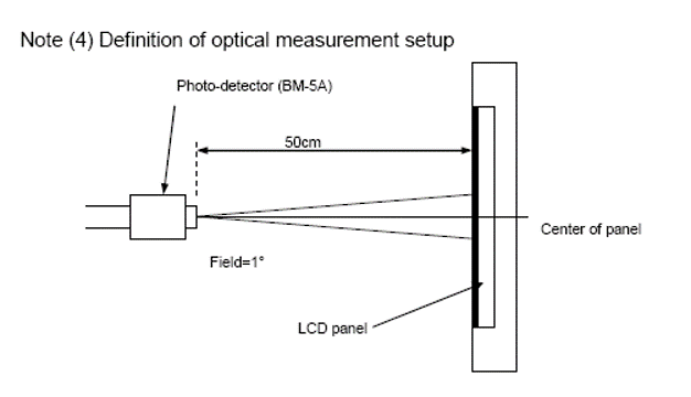
4. Optical Characteristics
| Item | Symbol | Condition | Min. | Typ. | Max. | Unit | Note | |
| Brightness | Bp | θ=0° F=0° | – | 350 | – | Cd/m2 | 1 | |
| Uniformity | ⊿Bp | 70 | – | – | % | 1,2 | ||
| Viewing Angle | 3:00 | Cr≥10 | – | 60 | – | Deg | 3 | |
| 6:00 | – | 45 | – | |||||
| 9:00 | – | 60 | – | |||||
| 12:00 | – | 60 | – | |||||
| Contrast Ratio | Cr | θ=0° F=0° | 300 | 500 | – | 4 | ||
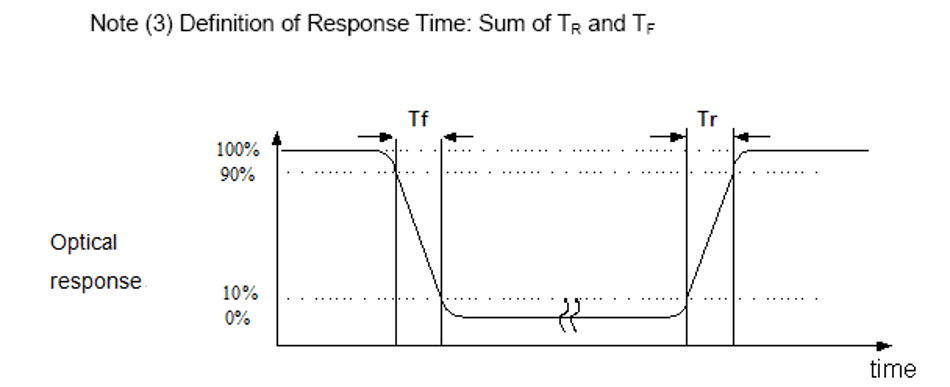
| Response Time | Tr | – | 10 | – | ms | 5 | ||
| Tf | – | 10 | – | ms | ||||
| Color of CIE Coordinate | W | x | θ=0° F=0° | 0.28 | – | 1,6 | ||
| y | 0.33 | – | ||||||
| R | x | 0.51 | – | |||||
| y | 0.34 | – | ||||||
| G | x | 0.31 | – | |||||
| y | 0.56 | – | ||||||
| B | x | 0.15 | – | |||||
| y | 0.14 | – | ||||||
| NTSC Ratio | S | 50 | 60 | – | % | |||

 5. Reliability Test Items and Criteria
| No | Test Item | Test condition | Criterion |
| 1 | High Temperature Storage | 60℃±2℃ 96H Restore 2H at 25℃ Power off | 1. After testing, cosmetic and electrical defects should not happen. 2. Total current consumption should not be more than twice of initial value. |
| 2 | Low Temperature Storage | -20℃±2℃ 96H Restore 2H at 25℃ Power off | |
| 3 | High Temperature Operation | 50℃±2℃ 96H Restore 2H at 25℃ Power on | |
| 4 | Low Temperature Operation | 0℃±2℃ 96H Restore 4H at 25℃ Power on | |
| 5 | High Temperature/Humidity Operation | 40℃±2℃ 90%RH 96H Power on | |
| 6 | Temperature Cycle | – 20℃←-– – – – – – – – →60℃ 30min 5min 30min after 5 cycle, Restore 2H at 25℃ Power off | |
| 7 | Vibration Test | 10Hz~150Hz, 100m/s2, 120min | Not allowed cosmetic and electrical defects. |
| 8 | Shock Test | Half- sine wave,300m/s2,11ms |
Note: Operation: Supply 3.3V for the logic system. The inspection terms after reliability test, as below
| ITEM | Inspection |
| Contrast | CR>50% |
| IDD | IDD<200% |
| Brightness | Brightness>60% |
| Color Tone | Color Tone+/-0,05 |
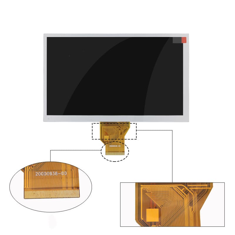
6. LCM outline Drawing 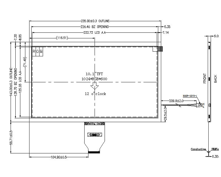 7. Precautions for Use of LCD Modules 7.1 Handling Precautions
- The display panel is made of glass. Do not subject it to a mechanical shock by dropping it from a high place, etc.
- If the display panel is damaged and the liquid crystal substance inside it leaks out, be sure not to get any in your mouth, if the substance comes into contact with your skin or clothes, promptly wash it off using soap and water.
- Do not apply excessive force to the display surface or the adjoining areas since this may cause the color tone to vary.
- The polarizer covering the display surface of the LCD module is soft and easily scratched. Handle this polarizer carefully.
- If the display surface is contaminated, breathe on the surface and gently wipe it with a soft dry cloth. If still not completely clear, moisten the cloth with one of the following solvents:
- Isopropyl alcohol
- Ethyl alcohol
Solvents other than those mentioned above may damage the polarizer. Especially, do not use the following:
- Water
- Ketone
- Aromatic solvents
- Do not attempt to disassemble the LCD module.
- If the logic circuit power is off, do not apply the input signals.
- To prevent destruction of the elements by static electricity, be careful to maintain an optimum worka. Be sure to ground the body when handling the LCD modules. b. Tools required for assembly, such as soldering irons, must be properly ground. c. To reduce the amount of static electricity generated, do not conduct assembly and other work under dry d. The LCD Module is coated with a film to protect the display surface. Be care when peeling off this protective film since static electricity may be generated.
7.2 Storage precautions
- When storing the LCD modules, avoid exposure to direct sunlight or to the light of fluorescent lamps.
- The LCD modules should be stored under the storage temperature range. If the LCD modules will be stored for a long time, the recommend condition is: Temperature : 0℃ ~ 40℃ Relatively humidity: ≤80%
- The LCD modules should be stored in the room without acid, alkali and harmful gas.
7.3 The LCD modules should be no falling and violent shocking during transportation, and also should avoid excessive press, water, damp and sunshine.
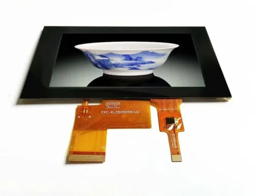
2) 10 inch 1280*800 IPS Touch LCD

VIS101IPS02C is a 10.1-inch touch TFT LCD module model that adopts IPS type LCD with a 1280*800 resolution. CTP (Capacity Touch Panel) has been added.
We also supply LCD with an HDMI converter for your requirements.
Based on this LCD’s wide view angle and high stability, this type of LCD display module can be widely used in smart homes, electronic restaurant menus, industrial instruments, vehicle displays, and other products.
FPCA pin defines & shape alignment, CTP touch, and backlight brightness can all be customized.
| Panel From | AUO/BOE |
|---|---|
| Panel Size | 10.1 inch |
| LCM Model | VIS101IPS02C |
| Panel Type | a-Si IPS LCD, LCM module with Touch |
| Resolution | 1280(H) X 800(V) |
| Luminance | 400 cd/m² (Typ.) |
| Display Area |
216.96*135.60 (mm) |
| Outline | 228.6*148.8*2.6 (mm) |
| Interface Type | LVDS |
| View Direction | 6 o’clock |
| Touchscreen | All |
| Operating Temperature | -20 ~ 70 °C |
| Storage Temperature | -30 ~ 80 °C |
– Interface: LVDS
– BLU: 10*4 LED (10*LED in series and 4 groups in parallel) IBL=80mA, VBL=27V;
Can be designed as requirements.
– LCM outline dimension: 228.6(H)*148.8(V)*2.6(T)(mm)
Can be customized as requirements.
– Touch Panel
A capacitive touch panel was included.
The touch panel can be customized as requirements.